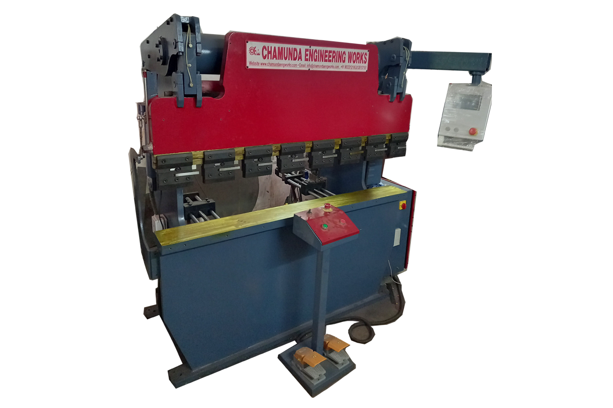
Salient Features
- Suitable for complex job bending
- Quick changeover for sample production & mass production
- 7'' color touch screen LCD for easy data entry
- Two axis atuomatic control - bending degree (Y Axis) & Back gauge (X-Axis) program
- Repeatable precise back gauge accuracy 0.1mm
- Wireless program data transfer between PC & controller
- Optional force control module screen
- Multiple bends with different back gauge positions can be programmed
Technical Features
- Bend angle programming method
- Direct bending degree entry as per job drawing
- Depth Mode degree program is also available
- The bending edge dimensions can be programmed as per individual bends
- Inside & out side edge dimensions can be defined in the program
- Automatic Bending degree with correction factor for each bend
- Automatic back gauge positions with correction factor for each bend
- Optional hardened tools & Manual / Automatic crowning
- The programs can be back-up by wireless connection to PC
Technical Details
| Metric Technical Specifications Sheet Conventional Hydraulic Press Brake Machine Series | ||||||||||||||||
|---|---|---|---|---|---|---|---|---|---|---|---|---|---|---|---|---|
| Model | Tonnage(MT) | Bending Capicity.(mm)(MS-UTS 45KG/mm2) | Table Size(mm) | Clear Passing(mm) | Ram Stroke(mm) | Open Height(mm) | Closed Height(mm) | Throat Depth(mm) | Ram Speeds (mm/sec.) | Motor (kw) HP | Overall Dimensions (mm) Approx. | Weight (kg)Approx. | ||||
| Approach | Pressing | Return | Length | Width | Height | |||||||||||
| CEWPBR-215 | 20 | 1.62 X 1500 | 125 X 1500 | 1250 | 100 | 250 | 150 | 100 | 40 | 6 | 38 | (2.2) 3 | 1800 | 1500 | 2000 | 1500 |
| CEWPBR-320 | 30 | 2 X 2000 | 125 X 2000 | 1700 | 100 | 280 | 180 | 200 | 30 | 7 | 30 | (2.2) 3 | 2300 | 1600 | 2000 | 2500 |
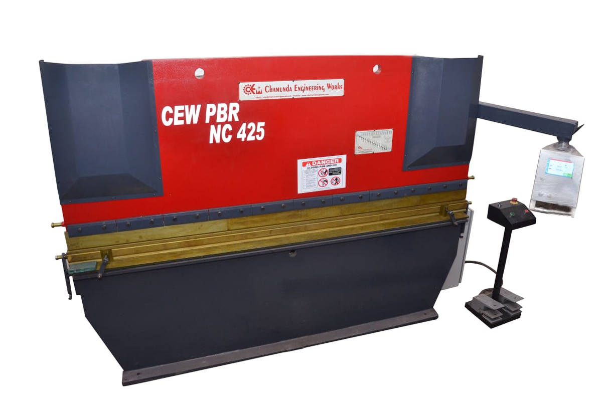
| CEWPBR-425 | 40 | 2 X 2500 | 170 X 2500 | 2000 | 100 | 280 | 180 | 200 | 50 | 6 | 50 | (3.75) 5 | 2700 | 1900 | 2100 | 3000 |
| CEWPBR-520 | 50 | 3.15 X 2000 | 170 X 2000 | 1500 | 100 | 280 | 180 | 200 | 48 | 6 | 48 | (3.75) 5 | 2300 | 1900 | 2200 | 3400 |
| CEWPBR-525 | 50 | 2.5 X 2500 | 170 X 2500 | 2000 | 100 | 280 | 180 | 200 | 48 | 6 | 48 | (3.75) 5 | 2900 | 1900 | 2200 | 3700 |
| CEWPBR-625 | 60 | 3.15 X 2500 | 170 X 2500 | 2000 | 150 | 330 | 180 | 200 | 36 | 5 | 36 | (3.75) 5 | 2900 | 2000 | 2400 | 3900 |
| CEWPBR-630 | 60 | 2.5 X 3000 | 170 X 3000 | 2500 | 150 | 330 | 180 | 200 | 36 | 5 | 36 | (3.75) 5 | 3200 | 2000 | 2300 | 4500 |
| CEWPBR-825 | 80 | 4 X 2500 | 170 X 2500 | 2000 | 150 | 350 | 200 | 200 | 45 | 6 | 48 | (5.5) 7.5 | 2800 | 2100 | 2400 | 4500 |
| CEWPBR-830 | 80 | 3.15 X 3000 | 170 X 3000 | 2500 | 150 | 350 | 200 | 200 | 45 | 6 | 48 | (5.5) 7.5 | 3400 | 2100 | 2400 | 5000 |
| CEWPBR-1025 | 100 | 5 X 2500 | 170 X 2500 | 2000 | 150 | 350 | 200 | 200 | 38 | 5 | 38 | (7.5) 10 | 2900 | 2200 | 2400 | 5600 |
| CEWPBR-1030 | 100 | 4 X 3000 | 170 X 3000 | 2500 | 150 | 350 | 200 | 200 | 38 | 5 | 38 | (7.5) 10 | 3400 | 2200 | 2400 | 6200 |
| CEWPBR-1230 | 125 | 5 X 3000 | 220 X 3000 | 2500 | 150 | 350 | 200 | 300 | 30 | 5 | 60 | (7.5) 10 | 3400 | 2500 | 2600 | 7000 |
| CEWPBR-1240 | 125 | 4 X 4000 | 220 X 4000 | 3000 | 150 | 350 | 200 | 300 | 30 | 5 | 60 | (7.5)10 | 4200 | 2500 | 2600 | 8700 |
| CEWPBR-1630 | 160 | 6 X 3000 | 220 X 3000 | 2500 | 150 | 350 | 200 | 300 | 30 | 5 | 60 | (11.2) 15 | 3400 | 2500 | 2600 | 8800 |
| CEWPBR-1640 | 160 | 5 X 4000 | 220 X 4000 | 3000 | 150 | 350 | 200 | 300 | 30 | 5 | 60 | (11.2) 15 | 4200 | 2500 | 2700 | 9800 |
| CEWPBR-2030 | 200 | 8 X 3000 | 220 X 3000 | 2500 | 200 | 410 | 210 | 300 | 20 | 5 | 50 | (15) 20 | 3500 | 2700 | 2700 | 9500 |
| CEWPBR-2040 | 200 | 6 X 4000 | 220 X 4000 | 3000 | 200 | 410 | 210 | 300 | 20 | 5 | 50 | (15) 20 | 4200 | 2700 | 2800 | 10500 |
| CEWPBR-3030 | 300 | 12 X 3000 | 300 X 3000 | 2500 | 200 | 460 | 260 | 300 | 19 | 5 | 30 | (18.75) 25 | 3500 | 2700 | 2800 | 12000 |
| CEWPBR-3040 | 300 | 10 X 4000 | 300 X 4000 | 3000 | 200 | 460 | 260 | 300 | 19 | 5 | 30 | (18.75) 25 | 4300 | 2800 | 2900 | 15000 |
| CEWPBR-4040 | 400 | 12 X 4000 | 400 X 4000 | 3000 | 250 | 500 | 250 | 400 | 20 | 5 | 40 | (22.4) 30 | 4300 | 2900 | 3000 | 18000 |
| Note : Above This Parameters will slightly change in NC version. | ||||||||||||||||
In air bending the dies are made at more of an acute angle (85′ or less than the angle to be formed.The only contact between the dies and the material occurs at the male punch and edge of the female die.The material is ”Air” bend rather than ”Coined” od ”Bottom” bend.
V= 6 to 8 x Material Thickness (t),When t < 4 KxLxSxt2
V= 8 to 12 x Material Thickness (t),When t > 4
Load, P = KxLxSxt2 \ 1000xV MT
| Press Brake Selection Guidelines | |
|---|---|
| Parameter | Unit |
| Plate Thickness (t) | mm |
| Ultimate Tensile Strength Of Plate (S) | kg/mm2 |
| Bending Length (L) | mm |
| ” Vee” Die Opening (V) | mm |
| Minimum Internal Radius ( R ) | mm |
| Minimum Flange (H) | mm |
| Bending Correction Factor (K) | 1.3 |
| Required Tonnage (P) | MT |
| The Force required for air bending can be calculated from the formula: | |