Manufacturers of Paver Blocks & Bricks Machine Plant
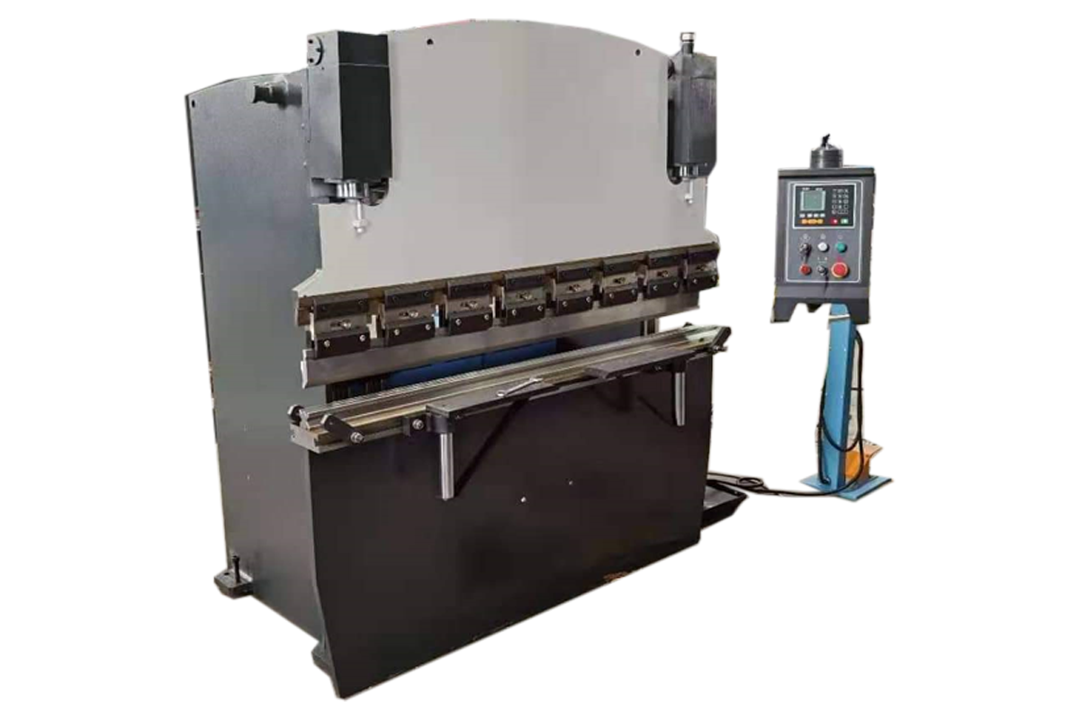
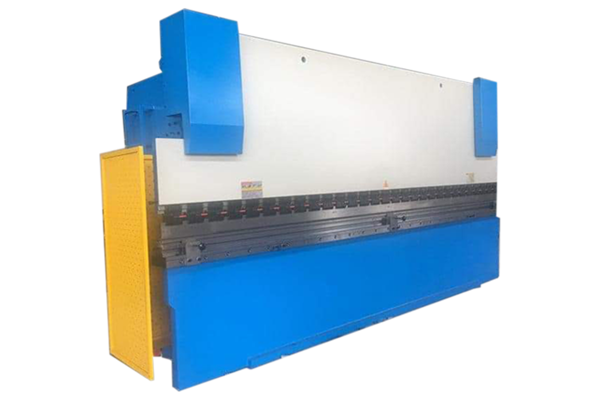
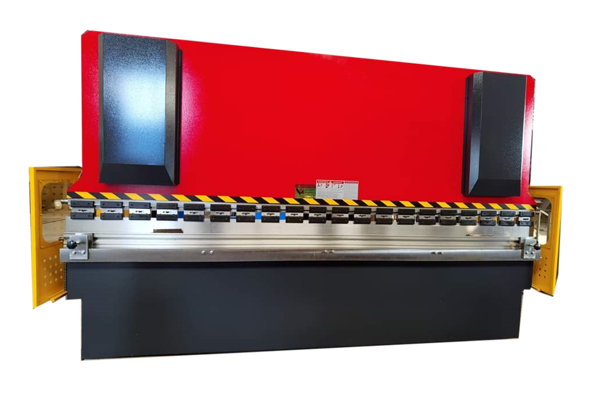
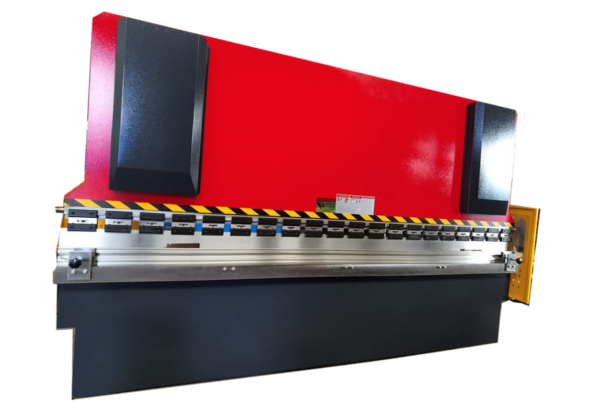
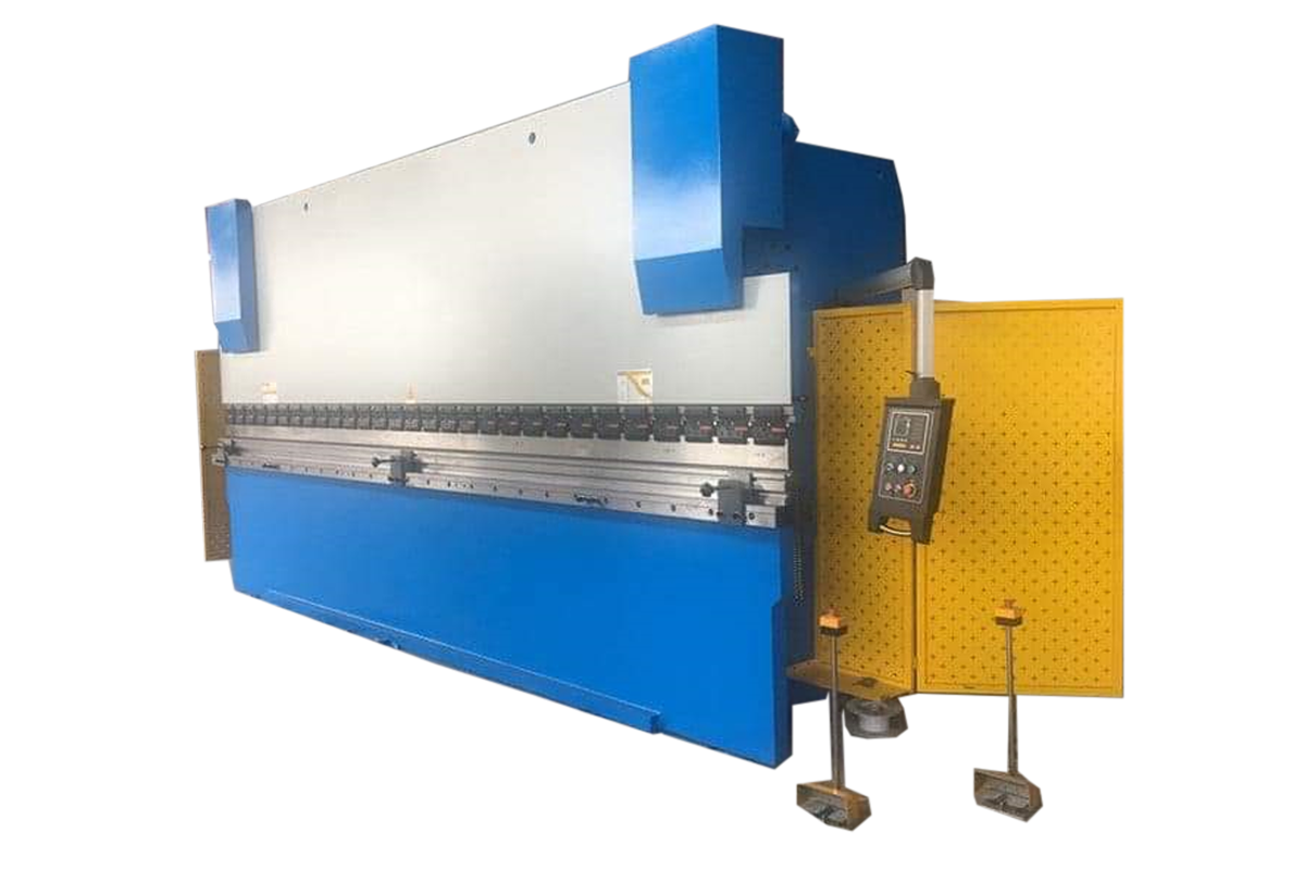
CNC Press Brake Machine
Salient Features
- The stable robust welded steel Frame made of ultrasonically and Tensile cested IS 2062 plate as per guidelines of IMTMA standards.
- Fast approach & fast return speed to save cycle time, slow pressing speed for better stroke control & bending accuracy, ensures high productivity
- Repeatability for ram position +0.05mm
- Compact cylinders & low pressure system due to rear cylinders. Also it gives better rigidity & load carrying capacity against fatigue failure
- Positive synchronisatio of cliders with welded torque tube gives better bending accurancy on both ends
- Moving work station with manual, single cycle & automatic mode for easy operation with emergency stop button
- NC upgradation passible on site
- All electrical & hydraulic component from reputed make
- Hydraulic cylinders made from seamiess honed tube, hardened & grounded chrome plated piston rod fitted with twin type zero leak PU seals
- Suitable for upgradation with special optional features
Technical Details
| Metric Technical Specifications Sheet CNC Synchro Press Brake Machine Series And Specifications. | ||||||||||||||||
|---|---|---|---|---|---|---|---|---|---|---|---|---|---|---|---|---|
| Model | Tonnage(MT) | Bending Capicity.(mm)(MS-UTS 45KG/mm2) | Table Size(mm) | Clear Passing(mm) | Ram Stroke(mm) | Open Height(mm) | Closed Height(mm) | Throat Depth(mm) | Ram Speeds (mm/sec.) | Motor (kw) HP | Overall Dimensions (mm) Approx. | Weight (kg)Approx. | ||||
| Approach | Pressing | Return | Length | Width | Height | |||||||||||
| CEWPBS-825 | 80 | 4 X 2500 | 180 X 2500 | 2000 | 150 | 350 | 200 | 200 | 100 | 9 | 65 | (7.5) 10 | 4000 | 1800 | 2500 | 5500 |
| CEWPBS-830 | 80 | 3 X 3000 | 180 X 3000 | 2500 | 150 | 350 | 200 | 200 | 100 | 9 | 65 | (7.5) 10 | 4500 | 1900 | 2500 | 6500 |
| CEWPBS-1025 | 100 | 5 X 2500 | 180 X 2500 | 2000 | 150 | 350 | 200 | 200 | 100 | 7 | 55 | (7.5) 10 | 4100 | 2200 | 2700 | 6500 |
| CEWPBS-1030 | 100 | 4 X 3000 | 180 X 3000 | 2500 | 150 | 350 | 200 | 200 | 100 | 7 | 55 | (7.5) 10 | 4600 | 2200 | 2700 | 7500 |
| CEWPBS-1230 | 125 | 5 X 3000 | 220 X 3000 | 2500 | 200 | 410 | 210 | 300 | 100 | 6 | 55 | (7.5) 10 | 4600 | 2300 | 2900 | 8500 |
| CEWPBS-1240 | 125 | 4 X 4000 | 220 X 4000 | 3000 | 200 | 410 | 210 | 300 | 100 | 6 | 55 | (7.5) 10 | 5500 | 2300 | 2900 | 9500 |
| CEWPBS-1630 | 160 | 6 X 3000 | 220 X 3000 | 2500 | 200 | 410 | 210 | 300 | 100 | 7 | 70 | (11.2) 15 | 4600 | 2300 | 2900 | 11000 |
| CEWPBS-1640 | 160 | 5 X 4000 | 220 X 4000 | 3000 | 200 | 410 | 210 | 300 | 100 | 7 | 70 | (11.2) 15 | 5500 | 2300 | 2900 | 13500 |
| CEWPBS-2030 | 200 | 8 X 3000 | 220 X 3000 | 2500 | 200 | 410 | 210 | 300 | 100 | 6 | 65 | (15) 20 | 4700 | 2400 | 3000 | 14000 |
| CEWPBS-2040 | 200 | 6 X 4000 | 220 X 4000 | 3000 | 200 | 410 | 210 | 300 | 100 | 6 | 65 | (15) 20 | 5500 | 2500 | 3100 | 17000 |
| CEWPBS-3030 | 300 | 12 X 3000 | 300 X 3000 | 2500 | 250 | 500 | 250 | 300 | 75 | 5.5 | 75 | (18.75) 25 | 4700 | 2600 | 3300 | 21000 |
| CEWPBS-3040 | 300 | 8 X 4000 | 300 X 4000 | 3000 | 250 | 500 | 250 | 300 | 75 | 5.5 | 75 | (18.75) 25 | 5500 | 2600 | 3500 | 26000 |
In air bending the dies are made at more of an acute angle (85′ or less than the angle to be formed.The only contact between the dies and the material occurs at the male punch and edge of the female die.The material is ”Air” bend rather than ”Coined” od ”Bottom” bend.
V= 6 to 8 x Material Thickness (t),When t < 4 KxLxSxt2
V= 8 to 12 x Material Thickness (t),When t > 4
Load, P = KxLxSxt2 \ 1000xV MT
| Press Brake Selection Guidelines | |
|---|---|
| Parameter | Unit |
| Plate Thickness (t) | mm |
| Ultimate Tensile Strength Of Plate (S) | kg/mm2 |
| Bending Length (L) | mm |
| ” Vee” Die Opening (V) | mm |
| Minimum Internal Radius ( R ) | mm |
| Minimum Flange (H) | mm |
| Bending Correction Factor (K) | 1.3 |
| Required Tonnage (P) | MT |
| The Force required for air bending can be calculated from the formula: | |
Since its commencement in 1991, Chamunda Engineering Works is instrumental in manufacturing Shearing Machine, Hydraulic Press Brake Machine, and Die Block. Our offered products range is well appreciated in the market, owing to their sturdy design, high impact and pressure bearing capacity, and dimensional accuracy.
Contact
-
-
-
Shed No.7, Parishram Industrial Estate, Jantanagar, Ramol, Ahmedabad-382449, Gujarat, India.
Contact Us
Register Address :
Shed No.7, Parishram Industrial Estate, Jantanagar, Ramol, Ahmedabad-382449, Gujarat, India.
Workshop Address :
Plot no.36, Sadbhav Estate, undrel Dhamatwan road, Dhamatwan Village, Bakrol, Gujarat, Ahmedabad - 382435
Email :
chamundaengworks10@gmail.com info@chamundaengworks.comMobile :
+91 - 90332 12195+91 - 81281 57161
© Copyright 2022 Chamunda Engineering Works. All Rights Reserved. | Design and Dizital Marketing by Innovative Ecom

